Proxmark3 community
Research, development and trades concerning the powerful Proxmark3 device.
Remember; sharing is caring. Bring something back to the community.
"Learn the tools of the trade the hard way." +Fravia
You are not logged in.
Announcement
Time changes and with it the technology
Proxmark3 @ discord
Users of this forum, please be aware that information stored on this site is not private.
Pages: 1
#1 2008-11-20 09:11:18
- d18c7db
- Contributor
- Registered: 2008-08-19
- Posts: 292
My set of antennas
OK I'm getting real excited now, the prox is built and it was high time I tested it, but for that I needed some antennas.
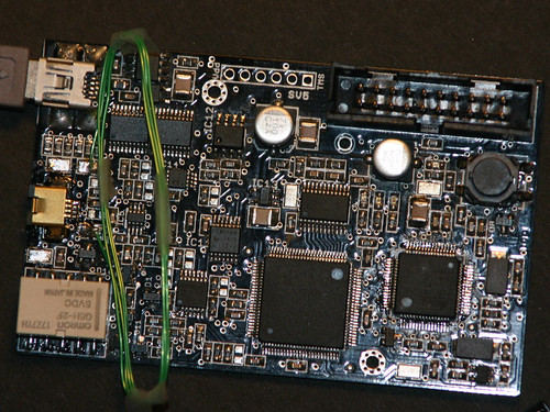
At first I used a piece of wirewrap "green wire" and rolled a 5 turn aircoil 43mm diameter, then experimentally played around with adding or removing a turn while issuing the tune command to get a voltage reading. It mostly sat around 1.3V except when I let the coil turns lose and unravelled and the coil looked like a deformed spring the voltage jumped to over 10V but that was not really an option for an antenna. I then returned to the 43mm diameter coil with 4 turns and taped the coil with sellotape to keep it together then started deforming it to see what difference that made. It looks like I got lucky as squashing it to an elongated and slighlty rectangular shape moved the voltage to about 16V.
This is how I ended up with this shape. It used to be straighter but the coil has been through a lot. It's soldered direct to the test pads as somebody forgot to order the mating hirose connector ![]() when buying the parts...
when buying the parts...
The picture below is a typical setup where a RFID snapper card is sandwitched between the proxmark3 antenna and a snapper feeder (card reader, the black thing that looks like a USB flash key)
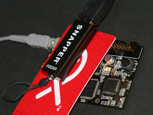
While in this close proximity, I issue the hi14asnoop command on the prox, then drive the snapper feeder with some python script for example issuing four consecutive list card commands in my python shell, like so:
>>> b.snapper_send_data(PN5XX_LIST_TAG)
sent: 0000FF04FCD44A0100E100
recv: 0000FF14ECD54B010104002004086B64BE08578002011000092600
>>> b.snapper_send_data(PN5XX_RF_OFF)
sent: 0000FF04FCD4320100F900
recv: 0000FF02FED533F800
>>> b.snapper_send_data(PN5XX_LIST_TAG)
sent: 0000FF04FCD44A0100E100
recv: 0000FF14ECD54B01010400200408DC78E708578002011000097800
>>> b.snapper_send_data(PN5XX_RF_OFF)
sent: 0000FF04FCD4320100F900
recv: 0000FF02FED533F800
>>> b.snapper_send_data(PN5XX_LIST_TAG)
sent: 0000FF04FCD44A0100E100
recv: 0000FF14ECD54B01010400200408E743D10857800201100009B800
>>> b.snapper_send_data(PN5XX_RF_OFF)
sent: 0000FF04FCD4320100F900
recv: 0000FF02FED533F800
>>> b.snapper_send_data(PN5XX_LIST_TAG)
sent: 0000FF04FCD44A0100E100
recv: 0000FF14ECD54B0101040020040841B32908578002011000099600
>>> b.snapper_send_data(PN5XX_RF_OFF)
sent: 0000FF04FCD4320100F900
recv: 0000FF02FED533F800
Then stopping the snoop (press the prox button) and issuing the hi14alist command we can see what the prox snooped. Note that the card's UID changes every time, so it moves through UIDs 086B64BE, 08DC78E7, 08E743D1, 0841B329 and these UIDs in the snooped prox output match the returned values in the python debug output.
>>>> hi14alist
recorded activity:ETU :rssi: who bytes ---------+----+----+----------- + 0: 0: TAG 04 00 + 1304: : 93 20 + 64: 0: TAG 08 6b 64 be b9 + 3471: : 93 70 08 6b 64 be b9 55 34 + 64: 0: TAG 20 fc 70 + 1488: : e0 50 bc a5 + 88: 0: TAG 08 57 80 02 01 10 00 09 94 da + 828164: : 26 + 5142: : 26 + 64: 0: TAG 04 00 + 1304: : 93 20 + 64: 0: TAG 08 dc 78 e7 4b + 3472: : 93 70 08 dc 78 e7 4b ac f2 + 64: 0: TAG 20 fc 70 + 1488: : e0 50 bc a5 + 88: 0: TAG 08 57 80 02 01 10 00 09 94 da + 612070: : 26 + 5142: : 26 + 1368: : 93 20 + 64: 0: TAG 08 e7 43 d1 7d + 3472: : 93 70 08 e7 43 d1 7d 84 67 + 64: 0: TAG 20 fc 70 + 1488: : e0 50 bc a5 + 88: 0: TAG 08 57 80 02 01 10 00 09 94 da + 578188: : 26 + 5144: : 26 + 64: 0: TAG 04 00 + 1303: : 93 20 + 3536: : 93 70 08 41 b3 29 d3 ab fc + 64: 0: TAG 20 fc 70
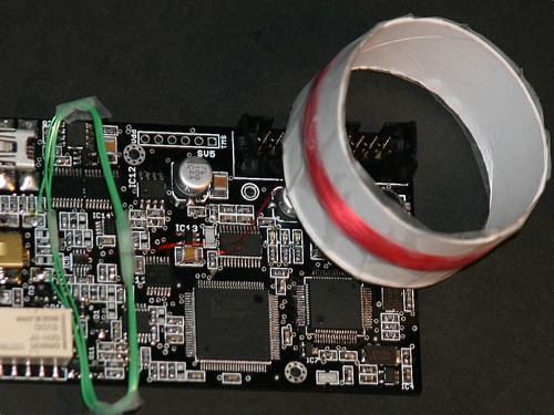
Finally for completeness I took Roel's idea of using a toilet paper roll, cut a slice and wound 150 turns of 0.125mm wire on it. I knew people had success in the past with around 100 turns so I started high and removed turns to get the tuning right. With 150 turns I used to get 45V on 125khz and about 20V on 136khz and as I removed turns these numbers moved closer to each other. There isn't much point going higher than 40V as the zenners will clip the voltage so I removed enough turns (lost count) until tune reported 29V at 125khz and 30V at 136khz. The picture below shows the final coil, sellotape is holding the coil to the TP roll ![]() and in the picture it's not actually soldered to the board as it's a little cumbersome to carry that around so I only fit it when needed. Currently I'm not doing any LF work so this coil isn't needed but it has successfully read some HID tags I have (in raw data mode).
and in the picture it's not actually soldered to the board as it's a little cumbersome to carry that around so I only fit it when needed. Currently I'm not doing any LF work so this coil isn't needed but it has successfully read some HID tags I have (in raw data mode).
Last edited by d18c7db (2008-11-20 09:33:00)
Offline
#2 2008-11-25 00:57:07
- d18c7db
- Contributor
- Registered: 2008-08-19
- Posts: 292
Re: My set of antennas
After experimenting with the coil designs above, I wanted to make something that was more robust and portable.
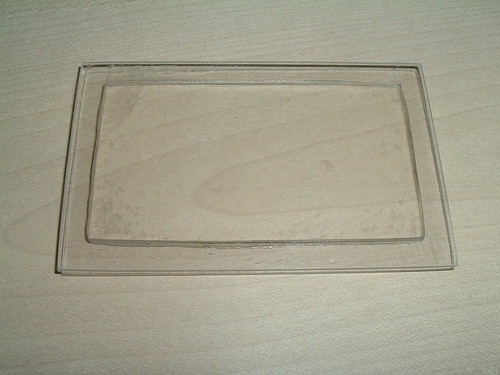
I took an old CD case and cut four rectangles out of it by using a ruler and a box cutter. Scour a line on the CD case and bend along it so the CD case snaps along the line, this is similar to cutting glass.
Two of the cut rectangles are the size of the proxmark3 PCB 80x50mm while the other two rectangles are 70x40mm. Epoxy the two smaller rectangles together then epoxy the resulting block between the larger two rectangles in the approximate centre as in the picture below. This makes up the coil former with a groove approximately 5mm deep and 2mm wide.

The theory for a rectangular multilayer coil 40x70mm with a coil cross-section of 2x1mm comes out with 107 turns so I started with 120 turns as in the picture below

Next I tuned tuned it by removing a few turns at a time. Originally I thought I might be able to tape the coil right next to the PCB but the very close proximity to the ground plane of the PCB messes up with the coil so I had to place a spacer (the foam pad).

With 110 turns and a foam pad 13mm thick the tuning comes up with these values.
> tune
# LF antenna @ 23 mA / 29406 mV [1273 ohms] 125Khz
# LF antenna @ 21 mA / 24975 mV [1187 ohms] 134Khz
# HF antenna @ 47 mA / 11053 mV [235 ohms] 13.56Mhz
The reason you see four wires from the antenna to the PCB is because I also placed the HF antenna on the same coil former as the LF, see picture below.

The HF coil was wound stuck on a piece of wide selotape with 4 turns in the shape of a rectangle 65x13mm then the wide piece of sellotape was stuck to the coil former made out of the CD case. It gets about 11V which turns out is plenty to activate and read a HF tag.
The LF antenna can read an HID tag to produce a waveform like the one below.
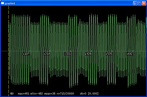
Which was then successfully replayed to a reader and recognized as valid.
Last edited by d18c7db (2008-11-25 06:08:48)
Offline
#3 2008-12-17 14:28:47
- n0t
- Contributor
- Registered: 2008-11-24
- Posts: 26
Re: My set of antennas
Nice job d18c7db!
Where did you get the 0.125mm wire? Is it coated?
Offline
#4 2008-12-18 07:23:23
- d18c7db
- Contributor
- Registered: 2008-08-19
- Posts: 292
Re: My set of antennas
Just standard enamel winding wire avalable from most electronic stores.
Offline
#5 2009-01-15 03:43:56
- Dennyxiao
- Contributor
- Registered: 2008-11-01
- Posts: 43
Re: My set of antennas
About Hi14asnoop.
I test HI14asnoop. it prompt me
#db# unknown command.
What 's the problem ?
Offline
#6 2009-01-15 04:56:19
- d18c7db
- Contributor
- Registered: 2008-08-19
- Posts: 292
Re: My set of antennas
Did you try it in all lowercase?
Offline
#7 2009-01-17 11:42:21
- doob
- Member
- Registered: 2008-07-21
- Posts: 15
Re: My set of antennas
Sounds like you have prox.exe and osimage.s19 updated to support 14443A but you have not updated fpgaimage.s19.
In the later versions of software fpgaimage, bootimage and osimage have been split - you probably need to flash the fpga image
See this post:
Offline
#8 2009-03-31 21:37:39
- touf
- Contributor
- Registered: 2008-12-11
- Posts: 27
Re: My set of antennas
i can't get a proper waveform ...

but i am able to use HidFskDemod and it is returning the correct value, so my board is definitly working.
i'm issuing the following commands :
loread
losamples
norm
plot
is there anything i'm doing wrong ?
Offline
#9 2009-04-01 01:55:51
- d18c7db
- Contributor
- Registered: 2008-08-19
- Posts: 292
Re: My set of antennas
Try "losamples 2000" or some other bigger number to get more samples in the buffer, maybe you're just hitting a patch where the card isn't modulating the waveform.
Last edited by d18c7db (2009-04-01 01:56:24)
Offline
#10 2009-04-01 08:35:01
- edo512
- Contributor
- Registered: 2008-10-07
- Posts: 103
Re: My set of antennas
i can't get a proper waveform ...
i'm issuing the following commands :
loread
losamples
norm
plotis there anything i'm doing wrong ?
A bit of self promotion: Try to read my manual at this page, you will find step by step instructions there... and let me know if you think things could be clearer!
Ed
Offline
#11 2009-04-01 15:26:41
- touf
- Contributor
- Registered: 2008-12-11
- Posts: 27
Re: My set of antennas
i've been all over your manual for quite some time now, thanks a lot, it is a big help .
but it couldn't help me to get rid of my problem.
i can see that there are short and long periods (8 and 10 samples long) on the waveform, it's just that the long seem to be unable to go higher than the short, like it has reached the maximum value.

and i do have 5 'long' periods and 6 'picks/short' periods. which indicates tht it is a HID tag

but why on earth am i not getting a waveform like that one ? 
i hope the pictures helped because i know that my english is not very good :-)
Last edited by touf (2009-04-01 15:27:05)
Offline
#12 2009-04-01 20:17:48
- d18c7db
- Contributor
- Registered: 2008-08-19
- Posts: 292
Re: My set of antennas
One reason why your waveform would have flat tops is that it's clipping. In other words the voltage from the antenna exceeds the maximum voltage on the zenner D11 of 47V though your antenna would have to be really well tuned for that to happen. Issue the tune command with and without a proxmark card in the antenna field and tell us what the results are.
Alternatively the waveform you see may well be normal, that's why is called FSK. It means Frequency Shift Keying. What you're expecting to see is some sort of amplitude modulation.
As you've noticed from my demodulator source code, I completely ignore the amplitude of the signal, I just look at the time between zero crossings, hence why the code still works with your type of waveform.
Last edited by d18c7db (2009-04-01 20:24:41)
Offline
#13 2009-04-01 21:52:42
- touf
- Contributor
- Registered: 2008-12-11
- Posts: 27
Re: My set of antennas
ok, thanks for the explication
Offline
#14 2010-03-08 19:55:53
- krater
- Member
- Registered: 2010-02-12
- Posts: 2
Re: My set of antennas
d18c7db:
can you write how you calculated your rectangular antenna ?
Offline
#15 2010-03-09 00:47:35
- d18c7db
- Contributor
- Registered: 2008-08-19
- Posts: 292
Re: My set of antennas
Yeah, Microchip application note AN710 page 12.
Offline
#16 2011-07-14 06:53:48
- spookyman166
- Member
- Registered: 2011-06-20
- Posts: 15
Re: My set of antennas
@d18c7db : Are you from NZ bro?
If you are CHEERS!!
How did you get your promark? and is it possible to supply a snoop of the snaper card and the bus terminal communicating?
Cheers,
Offline
#17 2011-07-14 07:37:15
- laser
- Contributor
- Registered: 2011-06-23
- Posts: 24
Re: My set of antennas
I have made a pcb antenna , but there is something wrong.
the picture is below

I can use it to reader, but can not snoop.
I can snoop a communication when use a antenna design by reol.(The same pm3 board)
**********************
Proxmark3电路板及相关读卡器销售
http://gezhidz.taobao.com
QQ:1074079485
MSN:xfpga@hotmail.com
手机:13113330725
**********************
Last edited by laser (2011-07-14 07:52:30)
Offline
Pages: 1