Proxmark3 community
Research, development and trades concerning the powerful Proxmark3 device.
Remember; sharing is caring. Bring something back to the community.
"Learn the tools of the trade the hard way." +Fravia
You are not logged in.
Announcement
Time changes and with it the technology
Proxmark3 @ discord
Users of this forum, please be aware that information stored on this site is not private.
#1 2009-04-23 11:35:52
- d18c7db
- Contributor
- Registered: 2008-08-19
- Posts: 292
Anyone experimented with driving the antenna at lower voltage?
I know it may seem like a weird question but I have an ultimate purpose. Currently the antenna is driven by the ACT244 octal drivers. These are rated for 5V operation and rightly so, as the board runs off the 5V USB bus.
What I want to know is whether someone has experimented driving antennas with AC244 chips rated for 2-6V operation (as per BizonGod's PM3.1b design) and driving the antenna through these at a lower voltage, say 3 or 3.3V?
Was the lower voltage sufficient to energize low and high frequency tags ? What was the voltage developed on the antenna? What was the read range? If 3V was too low for readings, what was the minimum voltage required for proper antenna operation? Etc, etc
Apart from the lower antenna drive voltage, another potential issue is that their drive capability drops from 24mA at 5V to 12mA at 3V.
(I wonder where have all the hardware hackers gone ![]() it's been too quiet lately)
it's been too quiet lately)
Offline
#2 2009-04-28 05:04:46
- d18c7db
- Contributor
- Registered: 2008-08-19
- Posts: 292
Re: Anyone experimented with driving the antenna at lower voltage?
To answer my own question, I replaced the antenna drivers with CMOS versions (74AC244) and run their supply pin 20 to an off board variable power supply. In the picture you can see small bits of paper insulating pin 20 from the PCB pad.
I can reliably read LO frequency tags down to 2 volts supply for the drivers and HI frequency tags down to 2.5 volts supply.
One noticeable difference with the CMOS drivers is that my tune command now returns half the voltage for HI (I used to get just over 10V, now I get 5V). The LO voltages haven't changed.
I plan to do another test in the next few days where I run the entire board off a lower voltage (except the ADC which is now the only component requiring 5V supply).
The point of all this, if it all goes well, is that it will show it's possible to design a new version board that can run off a lower overall system voltage, say 3 volts. That will of course require replacing the ADC with a 3V type, like an ADC08060 (60Mhz).
Once the board system voltage is lowered it will be a snap getting it to run off a battery (single cell Li or LiPo) with just LDOs without requiring DC/DC converters.
Last edited by d18c7db (2009-04-28 05:40:26)
Offline
#3 2009-04-28 06:18:26
- shinechou
- Contributor
- Registered: 2008-10-20
- Posts: 35
Re: Anyone experimented with driving the antenna at lower voltage?
...
Once the board system voltage is lowered it will be a snap getting it to run off a battery (single cell Li or LiPo) with just LDOs without requiring DC/DC converters.
wow, so great! hope it work!
Offline
#4 2009-04-28 06:45:05
- d18c7db
- Contributor
- Registered: 2008-08-19
- Posts: 292
Re: Anyone experimented with driving the antenna at lower voltage?
Ohh just realised, I didn't mean to imply that the current board could be made to run off a battery but a new design (new PCB required) could be made. There is no current pin compatible alternative to the ADC that will run off 3V so that isn't as easily replaced like the 244 drivers. I'm hoping BizonGod retuns to the forum soon with some progress updates on his redesign. I'd love to talk some hardware with him ![]()
Offline
#5 2009-04-28 10:25:14
- d18c7db
- Contributor
- Registered: 2008-08-19
- Posts: 292
Re: Anyone experimented with driving the antenna at lower voltage?
For those of you squeamish, look away now ![]()
And there you have it boys and girls. Some more board surgery. It's a bit hard to see as this pic was taken with a crappy iPhone, not the best for macro photography. Click on it for a larger (but not really much better) photo.
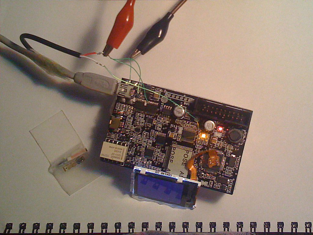
What was done? A USB cable was cut open, the positive power line cut and brought out, white wire is the USB power from the PC, red wire is the USB power at mini USB connector end. Normally these would be connected together so that the power from the PC reaches the card.
The PCB trace running between C19 and C44 was cut (ouch). This disconnects the power to the ADC. A wire connects from the ADC supply to the white USB 5V supply.
The red PM3 board supply wire connects to the 244 drivers supply lines and through the alligator clips to an external variable power source.
This setup allows me to power the PM3 from any voltage I choose, while the ADC alone runs off the USB 5V supply (as the chip can only run at 5V).
Long story short, I was able to read HI and LO tags (hi14areader and hidfskdemod) with a system voltage down to 3.26V
There was one more circuit surgery I forgot to mention, R53 was removed (and promptly lost as it fell on the carpet ![]() good thing they come in 10 packs). This change sets the ADC conversion range to .73 - 2.84 v or roughly +/- 1V centered on 1.75 because with the lowered system voltage, Vmid now becomes 3.26V/2 = 1.63V so we need the ADC to convert based on the new range.
good thing they come in 10 packs). This change sets the ADC conversion range to .73 - 2.84 v or roughly +/- 1V centered on 1.75 because with the lowered system voltage, Vmid now becomes 3.26V/2 = 1.63V so we need the ADC to convert based on the new range.
I couldn't really go much lower than 3.26V as the voltage after the LDO's was approaching 3V and uC supervisor IC7 would reset the ARM if the voltage drops below 3V.
So all this shows that the PM3 board (with a 3V version of the ADC) could function with a system voltage down to about 3V.
Offline
#6 2009-07-03 03:05:36
- samy
- Contributor
- From: los angeles, california
- Registered: 2009-06-18
- Posts: 148
- Website
Re: Anyone experimented with driving the antenna at lower voltage?
d1, nice.
Should we go find Bizon and sit outside his house to see what's new with his board?
I want to get a portable power source for the PM3. Any suggestions? I created a minty boost (http://www.ladyada.net/make/mintyboost/) but blew a capacitor somehow. Will have to see what messed up there, but do you suggest anything else?
In fact, I would like to run the minty boost off of a thin battery, such as a cell phone battery. Do you see anything wrong with this or any changes that need to happen with the minty boost to properly run from a cell battery? It would be convenient if the PM3 + battery could fit in a wallet (where two AA batterys will not fit in very well).
Offline
#7 2009-07-28 13:22:28
- d18c7db
- Contributor
- Registered: 2008-08-19
- Posts: 292
Re: Anyone experimented with driving the antenna at lower voltage?
3.3V system voltage only generated about 5V on the HF antenna, this was enough to read the only HF card I have. The card was flat against the antenna, so not a great reading distance. The LF antenna got about 10V iirc, again the tag was flat against the antenna for reading.
Offline
#8 2011-05-24 02:04:30
- uberdude
- Contributor
- Registered: 2011-05-24
- Posts: 17
Re: Anyone experimented with driving the antenna at lower voltage?
Any idea about the amount of current draw the Proxmark uses?
I'm also working on a protable slim version and thinking about using
http://www.sparkfun.com/products/8999
which is rated up to 100mA and has a nice small profile. I'd like to avoid using:
http://www.sparkfun.com/products/8290
since it has a larger profile and I'm trying to keep this as small as possible.
Any thoughts about how much current draw <100mA or <300mA a proxmark uses in either read or emulate mode?
Offline
#9 2011-05-25 01:57:21
- uberdude
- Contributor
- Registered: 2011-05-24
- Posts: 17
Re: Anyone experimented with driving the antenna at lower voltage?
Decided to do a few experiments tonight rather than wait for a response. Here are my results, your mileage may vary. The point is to use this in the HID standalone mode, so thats all I tested, nothing with HF.
I'm using the LF antenna from http://proxmark3.com/ so others can verify my results. I'm not sure how much of a difference the antenna makes, but figured for completeness I'd document it. Also, no data lines in the USB wire are connected since I won't have that in my portable version.
Standby after startup: 149mA
Red1 lit: 152mA, though subsequent return to Red1 lit, only draws ~100mA
Red1 +Red2 lit (read tag): 109 mA
Red1 +Green lit (emulate tag): 102 mA
Same current draw when slot 2 (orange) lit.
I went directly into HID mode, so I'm not sure if the drop in ~50mA from standby to HID mode is due to time or that HID mode just draws less current. It might also be due to a literal 'warm up' of the circuits. After doing some ops with the PM3, subsequent turnons only drew ~115 mA in standby.
Regardless, I now know that I need the bigger 5VDC converter that can handle up to 300mA to make a portable power supply for my proxmark III.
Offline
#10 2014-02-09 10:26:47
- gaucho
- Contributor
- From: France
- Registered: 2010-06-15
- Posts: 444
- Website
Re: Anyone experimented with driving the antenna at lower voltage?
hi all,
powering the board with lower voltage will make the board less able to read far tags cause the voltage on the antenna will be lower.
finally i think it is not interesting to lower the voltage, since it's easy nowadays to find a usb battery with 5V power supply.
I manufactured 20 pm3 boards and they are all not working.
Please help me with some reference measurements with oscilloscope.
in particular i'm worried about these 2 measures:
-my XT2 sine waveform is really low, about 500mVpp. is it normal?
...while my XT1 sine waveform is a good 4Vpp.
-the signal on HI_PWR is really low, which is the expected shape and amplitude?
...while on LO_PWR i can see a good 125kHz square waveform.
Offline